Month: June 2013

Windows Server 2012 – Create and Configure Shares

You may use the following method to create and configure a share (with basic settings) in Windows Server 2012.

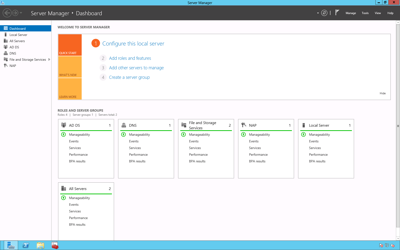
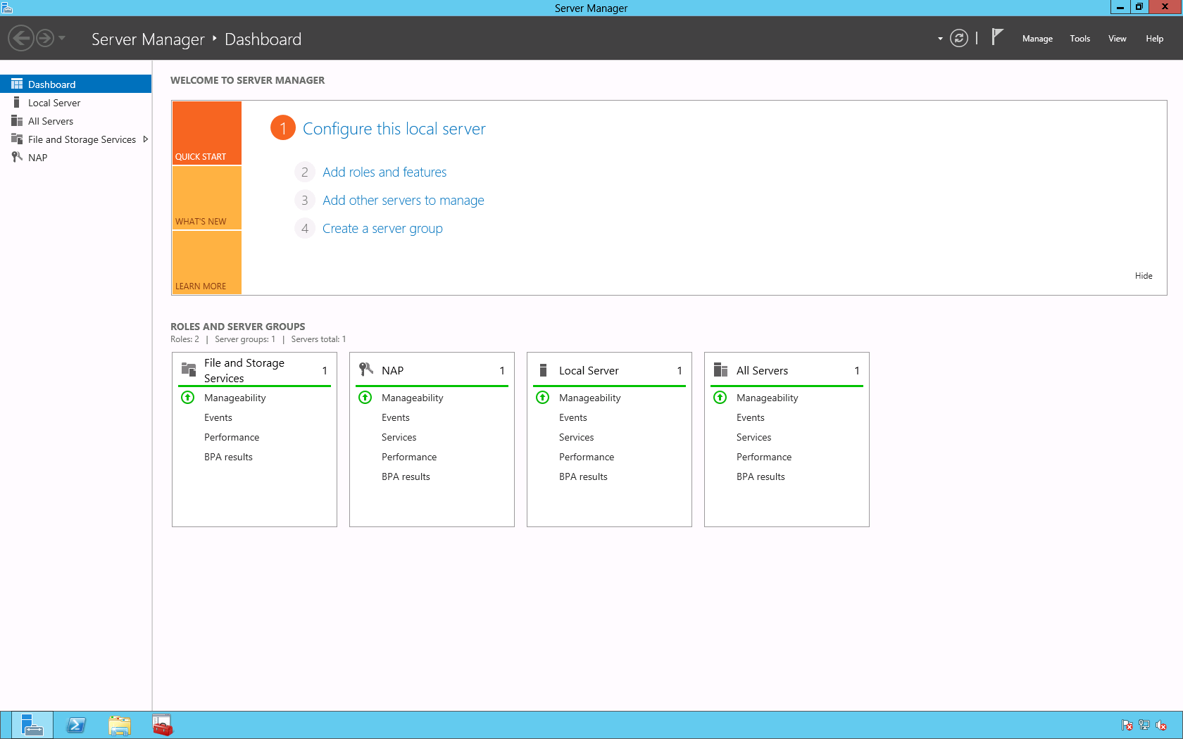
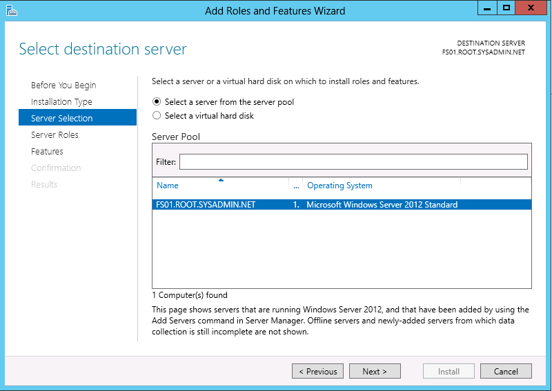
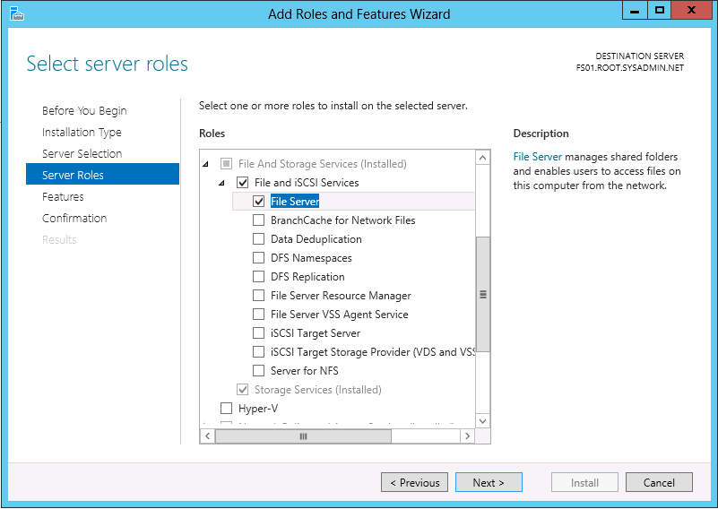
Begin by opening the Server Manager then navigating to File and Storage Services > Shares.

00

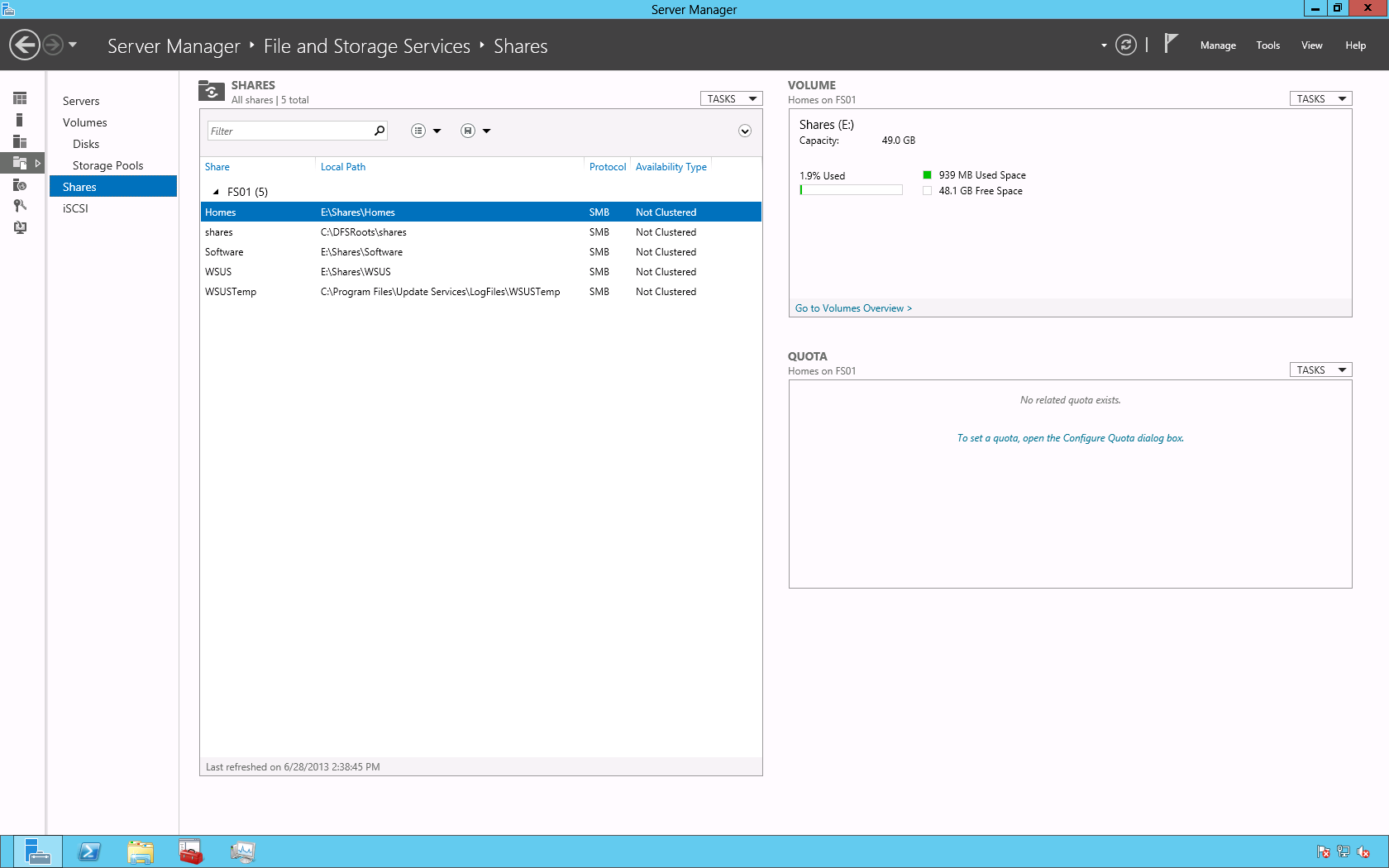
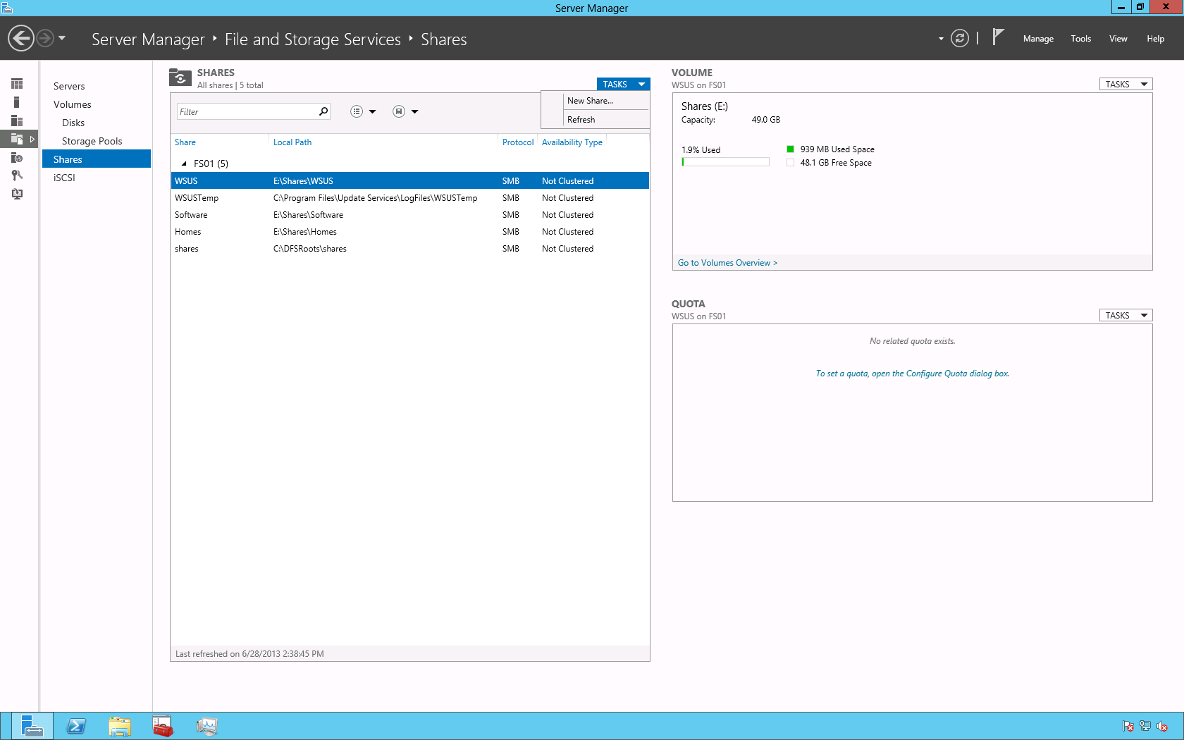
On the Shares page click TASKS > New Share….

01

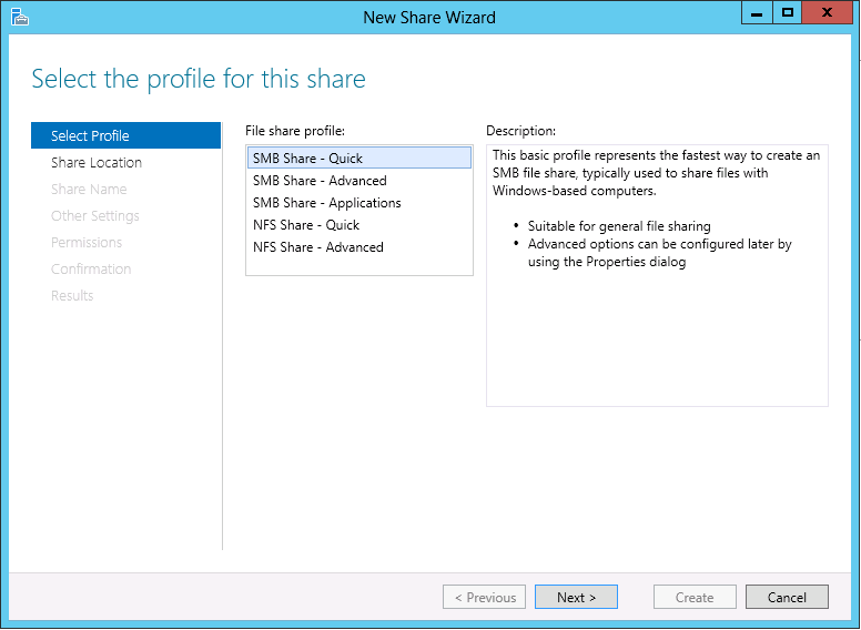
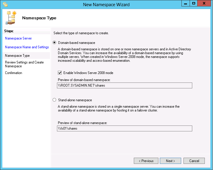
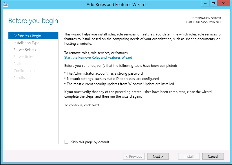
This is a very basic configuration (designed to get you accustomed to the platform) so in the New Share Wizard on the Select Profile page choose SMB Share – Quick then click Next >.

02

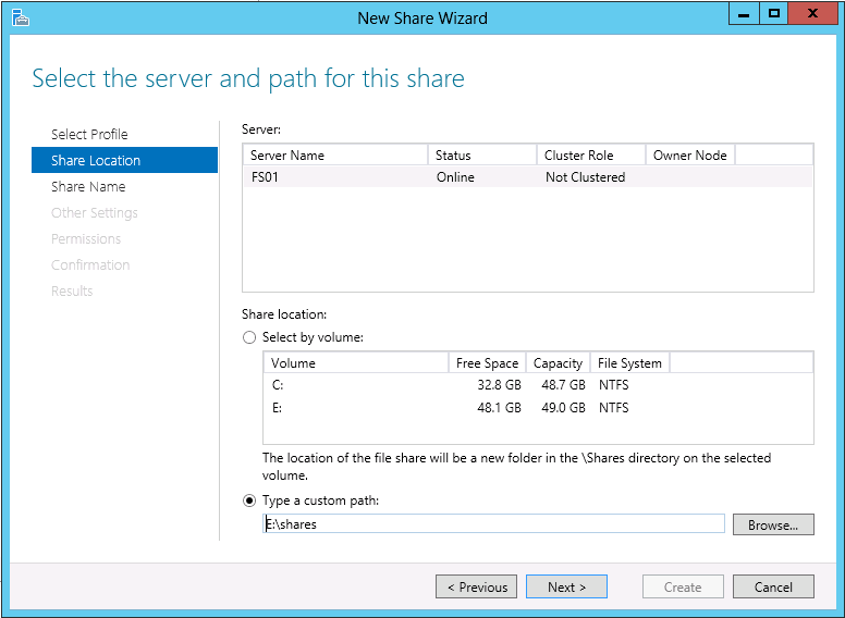
On the Share Location page choose the location of the share then click Next >. In this example, I chose a custom location of E:\shares.

03

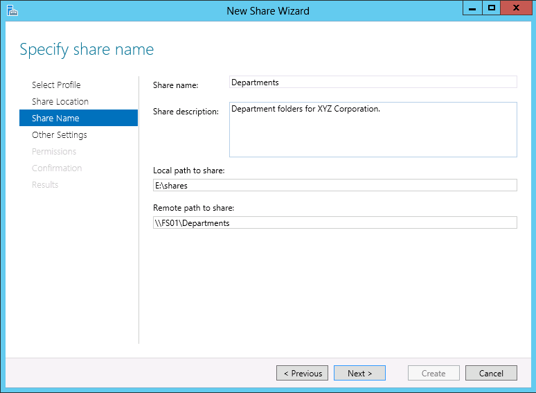
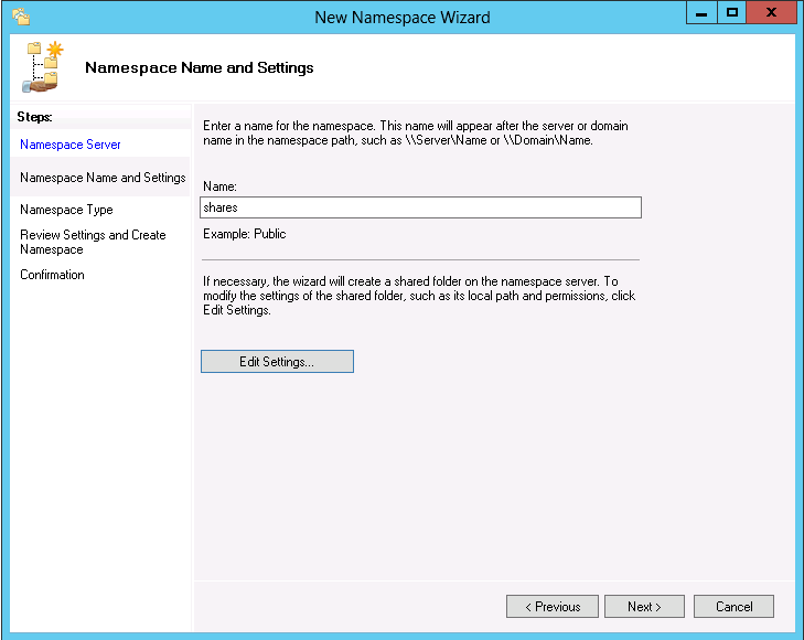
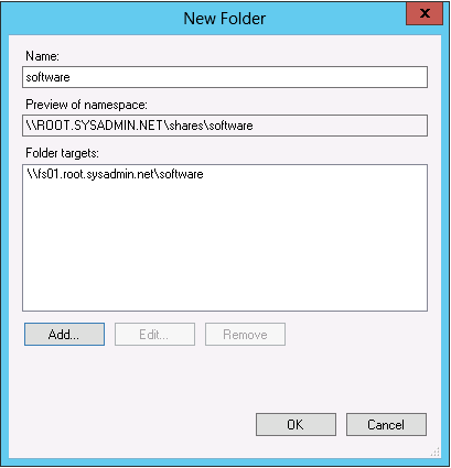
On the Share Name page type the name of the share and add a description (optional) then click Next >.

04

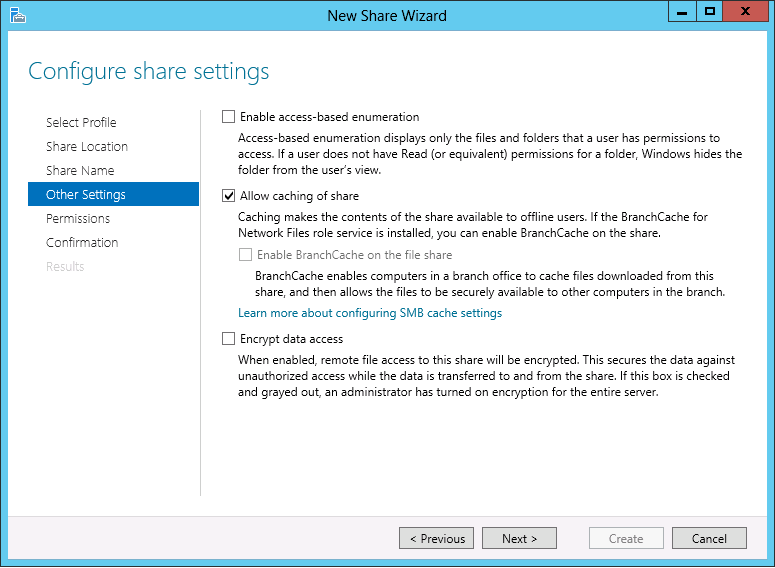
On the Other Settings page leave the default setting (Allow caching of share) then click Next >.

05

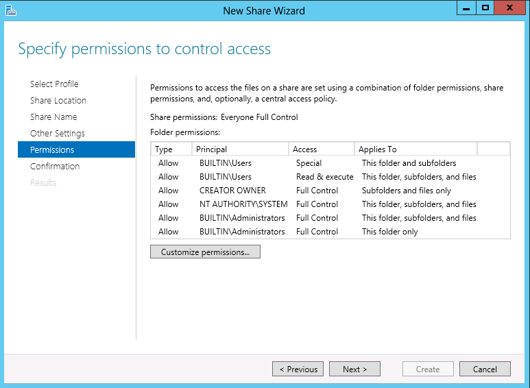
On the Permissions page you may click the Customize permissions… button the create a custom set of permissions for your share. After customizing click Next >.

06

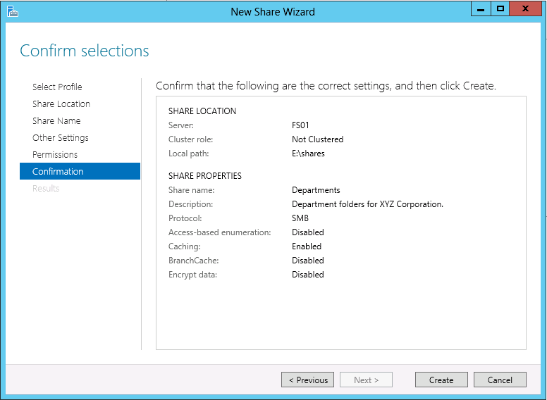
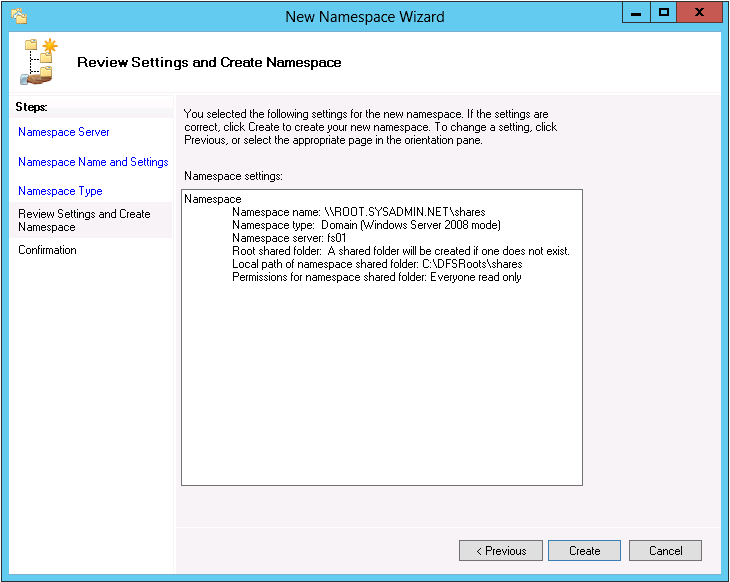
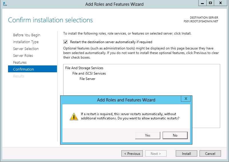
On the Confirmation page verify your configuration then click Create.

07

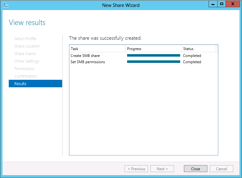
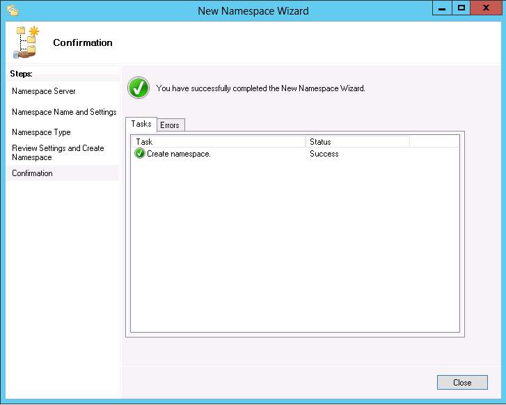
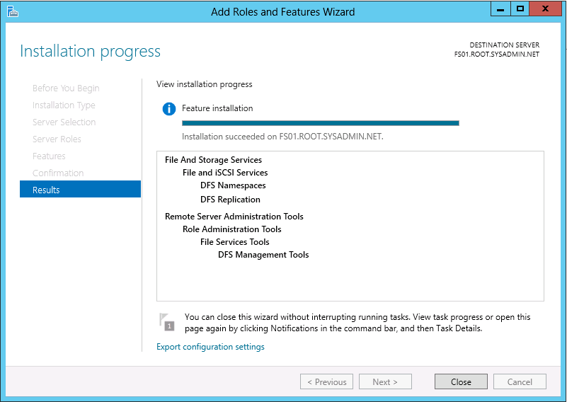
The Results page will inform you if the creation of the share was successful or unsuccessful. In this example, the creation was successful so click Close.

08

Enjoy!


Microsoft Windows Server 2012 – Distributed File System (DFS) Configuration

Distributed File System (DFS) allows you to share folders that are located on multiple servers using a consistent and logical namespace. Microsoft Windows Server 2012 allows you to add the DFS role (namespace and replication). After you add the DFS role you may use the following method to configure the namespace for your organization.

In Microsoft Windows Server 2012 select DFS Management on the start menu.

00

In the DFS Management console right click Namespaces and select New Namespace….

06

In the New Namespace Wizard dialog box, on the Namespace Server page click Browse…, then begin typing the name of the server that will host the name space, click OK. Lastly, click Next > on the New Namespace Wizard dialog box.

01

On the Namespace Name and Settings page enter the settings for your organization then click Next >. For this example I will type shares in order to make the namespace \\root.sysadmin.net\shares.

02

On the Namespace Type page select the appropriate setting for your environment then click Next >. In this example I will be using Domain-based namespace.

03

On the Review Settings and Create Namespace page review your settings then click Create, if they are correct.

04

On the Confirmation page you will be informed if the namespace was added successfully. If it was successful then click Close.

05

Next, right click the newly created namespace in the DFS Management console and select New Folder….

10

In the New Folder dialog box enter the next folder in the namespace and add it’s target by clicking Add… and adding the path in the Add Folder Target dialog box, then click OK.

07

08

Lastly, test the DFS configuration by connecting to the share using the newly created DFS namespace.

Enjoy!


Virtual Drive – Solution

If you ever find yourself in a situation where you need to mount an ISO you may use the application Virtual CloneDrive. The link below will provide a download link:

http://www.slysoft.com/en/download.html

Enjoy!


Microsoft Windows Server 2012 – Install Distributed File System (DFS) Role


You may use the following method to install the Distributed File System (DFS) role on a server running the Windows Server 2012 operating system (OS). The link below will direct you to a Microsoft TechNet article that provides a detailed description of DFS.

In the Microsoft Windows Server 2012 Server Manager dashboard click Add roles and features.

00

In the Add Roles and Features Wizard > Before You begin page click Next >.

01

On the Installation Type page select Role-based or feature-based installation and click Next >.02

On the Server Selection page select the appropriate server and click Next >.03

On the Servers Roles page navigate to File And Storage Services > File and iSCSI Services and select both DFS Namespaces and DFS Replication. When the Add features that are required for DFS Namespaces? dialog box appears click Add Features. Then, click Next >.040506

On the Features page click Next >.07

On the Confirmation page select the check box to Restart the destination server automatically if required (optional) and click Install.08

Click Close on the Results page after the installation succeeds.09

Lastly, you may configure your DFS namespace by clicking the DFS Management icon on the Start menu. This will open the DFS Management snap in.10

11

Enjoy!


Microsoft Windows Server 2012 – Adding the File Services Role

You may use the following method to install the File Server role on a server that is running the Windows Server 2012 operating system.

On the default menu of the Server Manager GUI click the Add roles and features option.

00

When the Add Roles and Features Wizard dialog box opens click Next > on the Before You Begin page.

01

On the Installation Type page select Role-based or feature-based installation.

02

On the Server Selection page use the Select a server from the server pool radio button and choose the correct server and click Next >.

03

On the Server Roles page navigate to File And Storage Services > File and iSCSI Services and check the box to select File Server then click Next >.

04

On the Features page click Next >.

05

On the Confirmation page select the check box to Restart the destination server automatically if required and click Yes in the Add Roles and Features Wizard prompt then click Install.

06

On the Results page click Close.

Enjoy!


Microsoft Windows Server 2012 – iSCSI LUN Configuration

You may use the following method to add storage disks, from an iSCSI SAN, to a server running the Microsoft Windows Server 2012 operating system (OS). All of the configuration will be completed from the operating system so this post assumes that the iSCSI initiator service is running and has been properly configured. Additionally, this post assumes that the SAN has been properly configured (volume, iSCSI IQN, LUN masking, etc.).

Begin by right clicking the Start menu and selecting Disk Management.

00


Next, right click the LUN that was configured on the SAN and select Online.

01


Next, right click the LUN that was brought Online and select New Simple Volume.

02


On the Welcome to the New Simple Volume Wizard page click Next >.

03


On the Specify Volume Size windows specify the size of the volume and click Next >. In this example it is 50 GB.

04


On the Assign Driver Letter or Path page you may assign a drive letter, use the LUN as an NTFS mounted drive or choose not to any assign any drive letter. In this example I will use the drive letter I.

05


On the Format Partition page keep the default values and click Next >.

On the Completing the New Simple Volume Wizard page verify the configuration and click Next >.

06


Lastly, on the Disk Management console you may see that the iSCSI disk is now available for use by the Windows Server 2012 operating system.

07Enjoy!


Cisco – Initial Router Configuration

You may use the following commands to configure a Cisco router out-of-box. The diagram below will provide you with a visual of the network topology. There are two (2) routers in this configuration utilizing the Internet Protocol (IP) addresses 172.16.25.1/30 and 172.16.25.2/30. I chose a subnet mask of 255.255.255.252 (/30) for the Wide Area Network (WAN) links because this link will only utilize two (2) IP addresses and the 255.255.255.252 subnet mask allows us to save IP addresses.

Network Topology


For the first step of the configuration I will verify that the router has no previous configuration by executing the show running-config and show startup-config commands. You may verify that this is a freshly restarted router with no previous configuration.

00


In the second step I will configure the user mode passwords (aux, console and vty), as well as the idle timeouts and a command to stop any router output from disrupting your text. The idea behind these first few configurations is to immediately secure the router.

01


Next, I will configure the enable mode password with the enable secret password command.

02


Next, I will configure the hostname of the router. In this example the hostname chosen is ORLSAN01.

03


Next, I will configure the message of the day (motd), login and exec process creation banner. These provide a warning to any individuals who would seek to login to the router without proper authorization.

04


08

Next, I will configure the Serial 0 and Ethernet 0 interfaces. Additionally, the Serial 0 interface will have the clock rate set in order to providing clocking to the second router in the network topology above. In a production environment this would not be necessary but for this demonstration it is.

05


09

Next, I will verify that the routing table only contains directly connected networks (no remote networks). Additionally, I will verify that pinging 172.16.30.1/24 will not work because there is no routing table entry for that network. In later configurations we will configure both static and dynamic routing.

0610

Next, I will save the configuration to NVRAM.

07


In the next portion of this demonstration I will configure the second router (ORLSAN02) but instead of showing all of the output I will only provide the final configuration via show running-config (with the hope of saving space).

11


From the show running-config you can see that the passwords are in clear text. By using the command service password-encryption and executing the show running-config command you can encrypt the passwords.


12


1314

Next, I will verify that the routing table on ORLSAN01 still only has directly connected routes (so the ping to 172.16.30.1/24 will fail).

15

Next, I will configure a static route to the 172.16.30.0/24 network and verify that the route is in the routing table. I chose an administrative distance of (AD) of 150 because these static routes will be a backup in the event that dynamic routing, to be configured later, fails. The S in the routing table signifies that the route is a static route, the C means the route is directly connected. If you ever see an R that means it is a RIP injected route.
16 
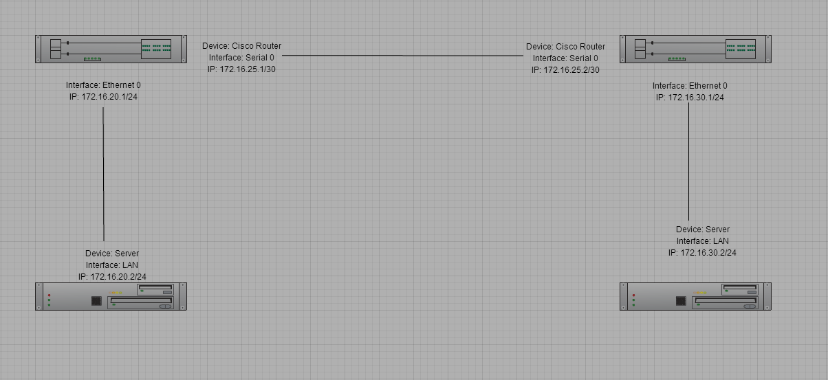
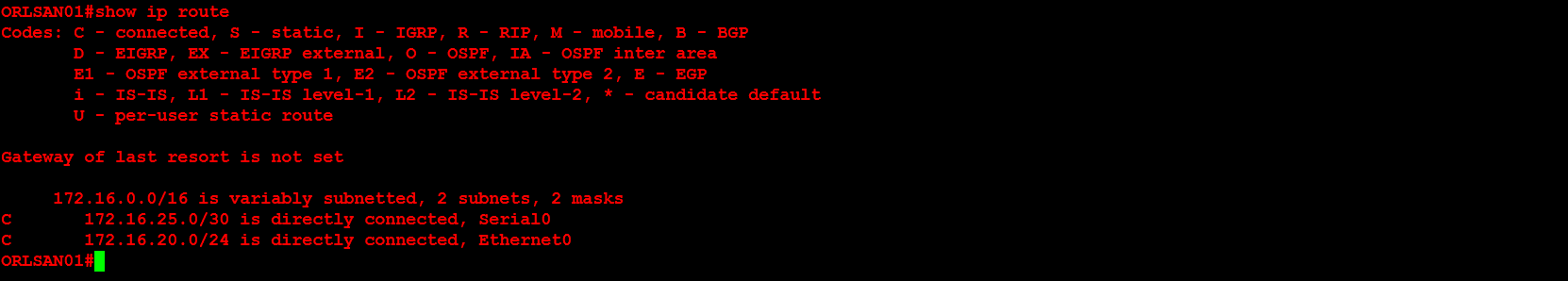
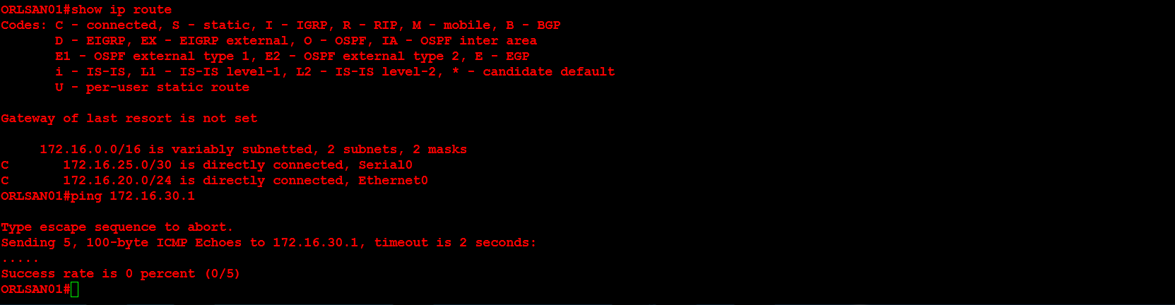
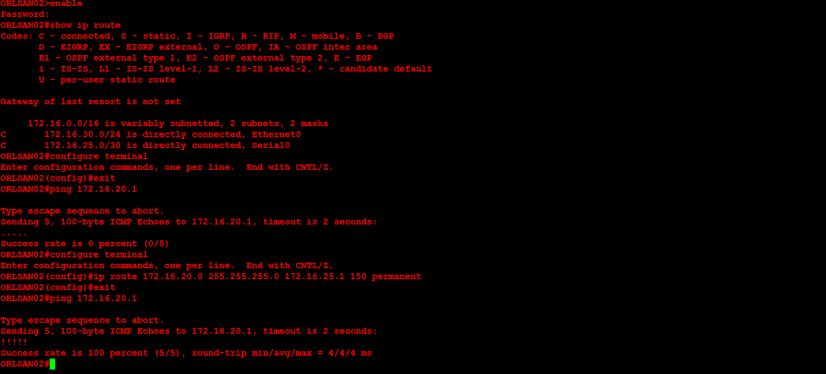
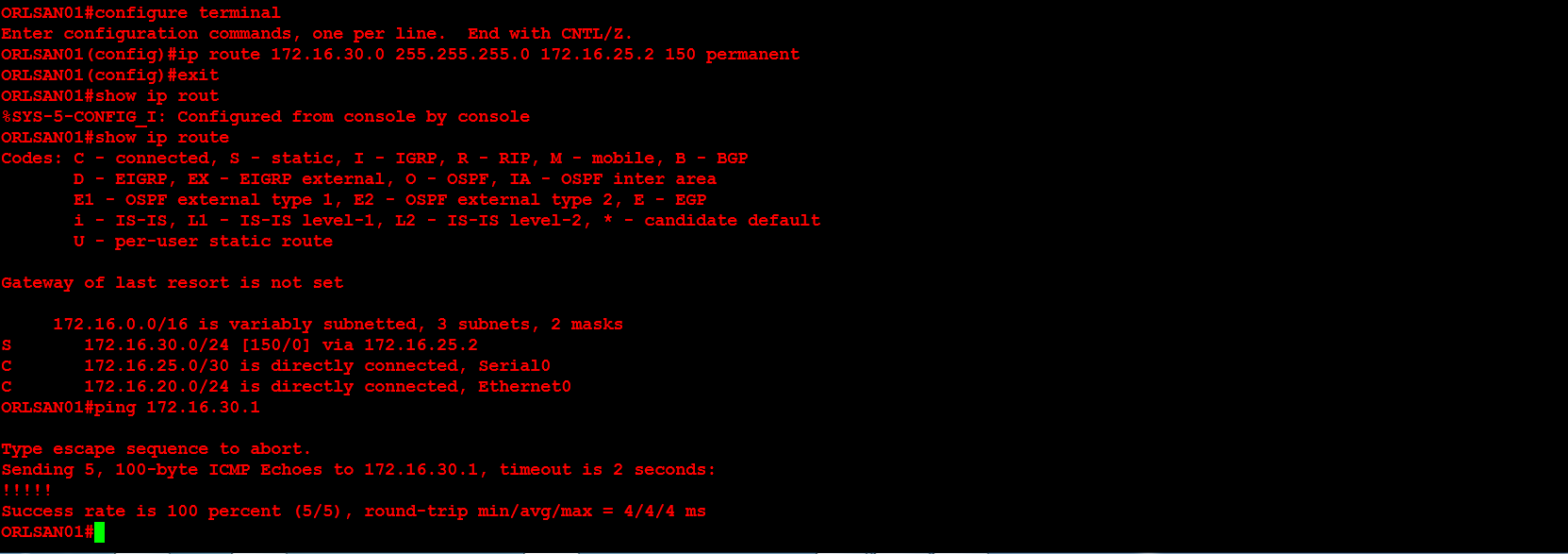
Next, I will configure ORLSAN02 with a static route to the 172.16.20.0/24 network, verify the route is in the routing table then ping 172.16.20.1.

17

Lastly, I will configure dynamic routing (RIPv2) on both routers, then verify that the RIP injected routes on ORLSAN01 and test the configuration by pinging 172.16.30.1 from the ORLSAN01 router.

18

19


Enjoy!


Microsoft Windows PowerShell – Server Uptime Script

You may use the following Microsoft Windows PowerShell (.ps1) script to create an HTML file daily that provides an uptime report for the servers in your Information Technology (IT) infrastructure.


=====START=====

<######################################################################

# Author : Bhavik Solanki 

# Date : 28th March 2012 

# Version : 1.0

# Desctiption : This script will help to monitor Server availability.

#
######################################################################>

Function GetStatusCode
{
Param([int] $StatusCode)
switch($StatusCode)
{
0 {“Success”}
11001 {“Buffer Too Small”}
11002 {“Destination Net Unreachable”}
11003 {“Destination Host Unreachable”}
11004 {“Destination Protocol Unreachable”}
11005 {“Destination Port Unreachable”}
11006 {“No Resources”}
11007 {“Bad Option”}
11008 {“Hardware Error”}
11009 {“Packet Too Big”}
11010 {“Request Timed Out”}
11011 {“Bad Request”}
11012 {“Bad Route”}
11013 {“TimeToLive Expired Transit”}
11014 {“TimeToLive Expired Reassembly”}
11015 {“Parameter Problem”}
11016 {“Source Quench”}
11017 {“Option Too Big”}
11018 {“Bad Destination”}
11032 {“Negotiating IPSEC”}
11050 {“General Failure”}
default {“Failed”}
}
}

Function GetUpTime
{
param([string] $LastBootTime)
$Uptime = (Get-Date) – [System.Management.ManagementDateTimeconverter]::ToDateTime($LastBootTime)
“Days: $($Uptime.Days); Hours: $($Uptime.Hours); Minutes: $($Uptime.Minutes); Seconds: $($Uptime.Seconds)”
}

#Change value of the following parameter as needed
$OutputFile = “\\server.domain.com\Information Technology Reports\Server Uptime\Server Uptime – ” + $(Get-Date -Format ‘MM_dd_yyyy HH_mm tt’) + “.html”
$ServerList = Get-Content “C:\Scripts\Server_Uptime.txt”

$Result = @()
Foreach($ServerName in $ServerList)
{
$pingStatus = Get-WmiObject -Query “Select * from win32_PingStatus where Address=’$ServerName'”

$Uptime = $null
if($pingStatus.StatusCode -eq 0)
{
$OperatingSystem = Get-WmiObject Win32_OperatingSystem -ComputerName $ServerName -ErrorAction SilentlyContinue
$Uptime = GetUptime( $OperatingSystem.LastBootUpTime )
}

$Result += New-Object PSObject -Property @{
ServerName = $ServerName
IPV4Address = $pingStatus.IPV4Address
Status = GetStatusCode( $pingStatus.StatusCode )
Uptime = $Uptime
}
}

if($Result -ne $null)
{
$HTML = ‘<style type=”text/css”>
#Header{font-family:”Trebuchet MS”, Arial, Helvetica, sans-serif;width:100%;border-collapse:collapse;}
#Header td, #Header th {font-size:14px;border:1px solid #98bf21;padding:3px 7px 2px 7px;}
#Header th {font-size:14px;text-align:left;padding-top:5px;padding-bottom:4px;background-color:#A7C942;color:#fff;}
#Header tr.alt td {color:#000;background-color:#EAF2D3;}
</Style>’

$HTML += “<HTML><BODY><Table border=1 cellpadding=0 cellspacing=0 id=Header>
<TR>
<TH><B>Server Name</B></TH>
<TH><B>IP Address</B></TD>
<TH><B>Status</B></TH>
<TH><B>Uptime</B></TH>
</TR>”
Foreach($Entry in $Result)
{
if($Entry.Status -ne “Success”)
{
$HTML += “<TR bgColor=Red>”
}
else
{
$HTML += “<TR>”
}
$HTML += ”
<TD>$($Entry.ServerName)</TD>
<TD>$($Entry.IPV4Address)</TD>
<TD>$($Entry.Status)</TD>
<TD>$($Entry.Uptime)</TD>
</TR>”
}
$HTML += “</Table></BODY></HTML>”

$HTML | Out-File $OutputFile
}

=====END=====

This script assumes you have a Microsoft Notepad (.txt) file titled Server_Uptime.txt in the C:\Scripts directory that contains the Fully Qualified Domain Name (FQDN) of each server for the report.

Below you may view a sample report. For security reasons, I have removed the FQDN of each server as well as it’s Internet Protocol (IP) address.

Server_Uptime


Microsoft Windows 7 – Modifying Profiles for Shortcuts, Folders or Files

You may use the following method, in Microsoft Windows 7, to modify the default profile and create changes in every users profile. For instance, you may add a particular shortcut, folder or file to the desktop of every single user. In Windows 7 navigate to:

C:\Users\Default\Desktop

Once you are in this directory you may place the shortcut, folder or file. Once the modification is complete any user who logs onto the computer, and creates a profile, will receive that shortcut, folder or file.

Additionally, you may use a group policy object (GPO) as an alternative solution if you have several users who need this shortcut, folder or file.

GPO Path: User Configuration\Preferences\Windows Settings

GPO Settings: Files | Folders | Shortcuts

Microsoft Windows 7 – Modifying Profiles for Shortcuts, Folders or Files


Enjoy!


Cisco – Configuring Cisco WRVS4400N Router

At my current employer we recently had a Cisco Small Business WRVS4400N Wireless-N gigabit security router with VPN reach the end of it’s life. I replaced the wireless access point and configured it using the documentation I created in the past. Below you will find a basic step by step guide for configuring the device as a wireless access point.

NOTE: Please keep in mind that this is a very basic configuration and your configuration should be planned with careful considering to your Information Technology (IT) infrastructure. Additionally, I have modified the input of the actual configuration for security purposes.

1. The default Internet Protocol (IP) of the device is 192.168.1.1/24. You may manually configure the IP address of a Windows host to 192.168.1.2/24 in order to connect to the device. The default username is admin and the default password is admin.

00


2. Upon logging into the device you will see the following web page.

01


3. Navigate to the Administration > Management page and configure the Router Username: and Router Password:. It is widely considered a best practice to change the default username and password in order to prevent unauthorized users from logging into the device.

02


4. Navigate to the Setup > LAN page and configure the Local IP Address: and Subnet Mask: of the device. In our environment we have an existing Dynamic Host Configuration Protocol (DHCP) server so the DHCP Server: settings under the Server Settings (DHCP) menu is configured as a DHCP Relay.

03

5. Navigate to the Setup > Time page and configure the time settings for the device. I chose to use the Set the local time using Network Time Protocol (NTP) automatically setting. Our Time Zone: setting is (GMT-05:00) Eastern Time (US & Canada).

04

6. Under the Wireless > Basic Settings page configure the Wireless Network Mode:, Wireless Channel: and the SSID settings.

05

7. Under the Wireless > Security Settings page configure the Security Mode: and Shared Secret: for the SSID configured in step 6.

06

8. I recommend you backup the configuration by navigating to Administration > Backup & Restore. Once you are redirected to this page click the Backup button and specify the directory where the backup configuration will be saved. I did have a previously saved backup configuration but I configured this Cisco wireless access point manually in order to document the process on this webpage.

07

Enjoy!