Category: Cisco

Microsoft Windows 10 – False Duplicate IP Address Detected

At my existing employer, it was brought to my attention that a number of VMware virtual machines running the Microsoft Windows 10 operating system were randomly dropping off the network, upon reboot. Viewing the properties of the network adapter confirmed that they were assigned static IP addresses. However, running ipconfig from the command prompt showed that they were assigned 169.254.x.x IP addresses.

Upon reviewing the logs I found the following error message: “The system detected an address conflict for IP address 0.0.0.0 with the system having network hardware address XX-XX-XX-XX-XX-XX. Network operations on this system may be disrupted as a result.” The XX-XX-XX-XX-XX-XX is the MAC address of a Cisco switch.

In summary, the root cause of this is Windows 10 performing an ARP probe at the time as the Cisco switch performing an ARP probe in order to maintain the IP device-tracking cache during IP device tracking. The Windows 10 host believes another node on the network is probing the address it’s assigned and must treat it as an IP address conflict.

The solution is to disable gratuitous ARPs on the switch or in the Windows 10 operating system. We chose to disable the gratuitous ARP in the Windows 10 operating system.

Additionally, more information may be found using the links below.


Cisco Unified Computing System – Diagnostics for the Unified Computing System (UCS)

The following is a step by step guide running the Cisco Unified Computing System blade diagnostic utility.

  1. Mount the ucs-blade-server-diags.1.0.1b.iso which may be found here.
  2. On the Unified Computing System Blade Server Diagnostics homepage select Offline Diagnostics (GUI).02
  3. On the UCS Blade Diagnostics v1.0(1b) page select < Accept  >.03
  4. On the UCS Blade Diagnostics UCS B200 M3 page select Diagnostic Tools > Tests > Comprehensive Tests > Run all comprehensive tests.04
  5. After the completion of the Comprehensive Tests the output will be provided.05-0105-02

Cisco – Delete All VLANs

You may use the following global configuration command to remove VLANs 2-1001 on a Cisco switch. This range is chosen because VLANS 1, 1002, 1003, 1004 and 1005 cannot be removed from a Cisco switch. This command may be used when a switch’s configuration needs to be deleted, in addition to erase startup-config, for a new deployment.

switch-01(config)#no vlan 2-1001


Cisco – Port Security

You may use the following method to configure port security on a Cisco switch. Additionally, this configuration will not use the switchport port-security violation {protect | restrict | shutdown} command in order to accept the default action of shutdown.

1. Verify the existing configuration, if any, exists on the switch port.

01


2. Navigate to the interface configuration prompt of the interface you would like to configure.

02


3. Enter the switchport mode access command.

03


4. Enter the switchport port-security command to enable port security.

04


5. Enter the switchport port-security maximum x command to define the maximum number of MAC addresses to define where x is the number of MAC address to define. The default value is to accept a maximum of (1) MAC address. In this example the maximum number is (2).

05


6. Enter the switchport port-security mac-address sticky to allow the switch to dynamically learn the first (2) MAC addresses.

06


7. Verify the port security configuration using the show running-config command or the show port-security interface FastEthernet 0/1 command.

07-1


07-2


Enjoy!


Cisco – Configure Cisco Catalyst 3560 VLANs

You may use the following method to configure Virtual LANs (VLANs) on a Cisco Catalyst 3560 switch. VLANs allow you to segment a layer 2 switched network by increasing the number of layer 2 broadcast domains and decreasing their size. Additionally, VLANs provide an added measure of network security.

Begin by entering global configuration mode with the configure terminal command.

Cisco – Configure Cisco Catalyst 3560 VLANs - 00

Next, use the vlan # command where the # sign is the number of the VLAN. Additionally, use the name “name” command to provide a custom description of the VLAN. In this example there are three created VLANS, 2 (Sales), 3 (Marketing) and 4 (Accounting).

Cisco – Configure Cisco Catalyst 3560 VLANs - 01

Lastly, you may verify the creation of the VLANs with the show vlan command.

Cisco – Configure Cisco Catalyst 3560 VLANs - 02

Enjoy!


Cisco – Configure Cisco Catalyst 3560 Switch Trunk

You may use the following method to configure a Cisco Catalyst3560 switch port as a trunk. In this example we will use the FastEthernet 0/24 port.

Begin by entering global configuration mode and specifying the port, FastEthernet 0/24, that will be configured as a trunk port.

Cisco - Configure Cisco 3560 Switch Trunk Port - 00

Next, we must specify the version of trunking we will implement. In this example we will implement IEEE 802.1q trunking which is specified by the switchport trunk encapsulation dot1q command.

Cisco - Configure Cisco 3560 Switch Trunk Port - 01

Next, we enable the trunk with the switchport mode trunk command. Note that this command will automatically negotiates to convert the link on the other end to a trunk link.

Cisco - Configure Cisco 3560 Switch Trunk Port - 02

Lastly, you may verify the trunk port with the show interface trunk command.

Cisco - Configure Cisco 3560 Switch Trunk Port - 03

Enjoy!


Cisco – OSPF Routing Protocol Configuration

Open Shortest Path First (OSPF) is an open standard routing protocol that may be implemented on routers from multiple vendors. In this example the OSPF routing protocol will be implemented on two (2) Cisco routers.

First, I will issue the show ip protocols command to verify there is no existing routing protocol running on the router. If there was another routing protocol with a lower administrative distance (AD) such as IGRP or EIGRP then the OSPF configuration would have been void until IGRP or EIGRP were turned off.

00

Next, I will enter global configuration mode by entering the command configure terminal. After that I enabled the OSPF routing protocol with the command router ospf 1. The number “1” is the process ID for OSPF and is only locally significant.

01

Next, I specified the networks to be advertised (172.16.20.0/24 and 172.16.25.0/3) using wildcards and placed them in area 0.

02

Next, I entered the command show ip protocols to verify that the OSPF routing protocol is enabled on this router. Additionally, I can verify that it is running under process “1” and verify the networks that are being advertised.

03

Next, I configured the OSPF routing protocol, using the same method in the previous steps, on the other router in this example.

04

Now I will verify that the 172.16.20.0/24 is being advertised by the ORLSAN01 router by enter the command show ip route.

05

Additionally, I can ping the ethernet 0 interface (172.16.20.1) on ORLSAN01 to verify Internet Protocol (IP) connectivity.

06

I will now make my way back to ORLSAN01 and view the routing table to verify that the 172.16.30.0/24 network from ORLSAN02 is being advertised. As in my previous example I will ping the ethernet 0 interface (172.16.30.1) on ORLSAN02 to verify IP connectivity.

07

They were no dropped packets in either example so this configuration is successful.

Enjoy!


Cisco – EIGRP Routing Protocol Configuration

You may use the following method to configure Enhanced Interior Gateway Routing Protocol (EIGRP) on your Cisco router(s).

Begin by entering privileged exec mode on your Cisco router by using the enable command.

00

Enter global configure mode by using the command configure terminal.

01

Type the command router eigrp [as] where [as] is the autonomous system number. The autonomous system number may be any number between 1 – 65535. The important part to remember is that the autonomous system numbers must be identical on each router in order for the EIGRP routers to exchange routing information.

02

Use the network x.x.x.x command to advertise the networks of your choosing where x.x.x.x is the classful address range of that particular network. In this particular example this router has 172.16.20.0/24 (ethernet 0) and 172.16.25.0/30 (serial 0) configured so I used the classful address range 172.16.0.0.

03

After configuring the other router in this example, with EIGRP and autonomous system number 250, we can now verify our configuration with the show ip protocols, show ip route and ping commands.

04

The show ip protocols command will display information regarding each routing protocol that is configured on your router. The show ip route command will display the routing table on your router. In this example, the C represents directly connected networks and the D represents the EIGRP advertised routes. Lastly, I used the ping command to verify network connectivity between the two routers.

Enjoy!


Cisco – Initial Router Configuration

You may use the following commands to configure a Cisco router out-of-box. The diagram below will provide you with a visual of the network topology. There are two (2) routers in this configuration utilizing the Internet Protocol (IP) addresses 172.16.25.1/30 and 172.16.25.2/30. I chose a subnet mask of 255.255.255.252 (/30) for the Wide Area Network (WAN) links because this link will only utilize two (2) IP addresses and the 255.255.255.252 subnet mask allows us to save IP addresses.

Network Topology


For the first step of the configuration I will verify that the router has no previous configuration by executing the show running-config and show startup-config commands. You may verify that this is a freshly restarted router with no previous configuration.

00


In the second step I will configure the user mode passwords (aux, console and vty), as well as the idle timeouts and a command to stop any router output from disrupting your text. The idea behind these first few configurations is to immediately secure the router.

01


Next, I will configure the enable mode password with the enable secret password command.

02


Next, I will configure the hostname of the router. In this example the hostname chosen is ORLSAN01.

03


Next, I will configure the message of the day (motd), login and exec process creation banner. These provide a warning to any individuals who would seek to login to the router without proper authorization.

04


08

Next, I will configure the Serial 0 and Ethernet 0 interfaces. Additionally, the Serial 0 interface will have the clock rate set in order to providing clocking to the second router in the network topology above. In a production environment this would not be necessary but for this demonstration it is.

05


09

Next, I will verify that the routing table only contains directly connected networks (no remote networks). Additionally, I will verify that pinging 172.16.30.1/24 will not work because there is no routing table entry for that network. In later configurations we will configure both static and dynamic routing.

0610

Next, I will save the configuration to NVRAM.

07


In the next portion of this demonstration I will configure the second router (ORLSAN02) but instead of showing all of the output I will only provide the final configuration via show running-config (with the hope of saving space).

11


From the show running-config you can see that the passwords are in clear text. By using the command service password-encryption and executing the show running-config command you can encrypt the passwords.


12


1314

Next, I will verify that the routing table on ORLSAN01 still only has directly connected routes (so the ping to 172.16.30.1/24 will fail).

15

Next, I will configure a static route to the 172.16.30.0/24 network and verify that the route is in the routing table. I chose an administrative distance of (AD) of 150 because these static routes will be a backup in the event that dynamic routing, to be configured later, fails. The S in the routing table signifies that the route is a static route, the C means the route is directly connected. If you ever see an R that means it is a RIP injected route.
16 
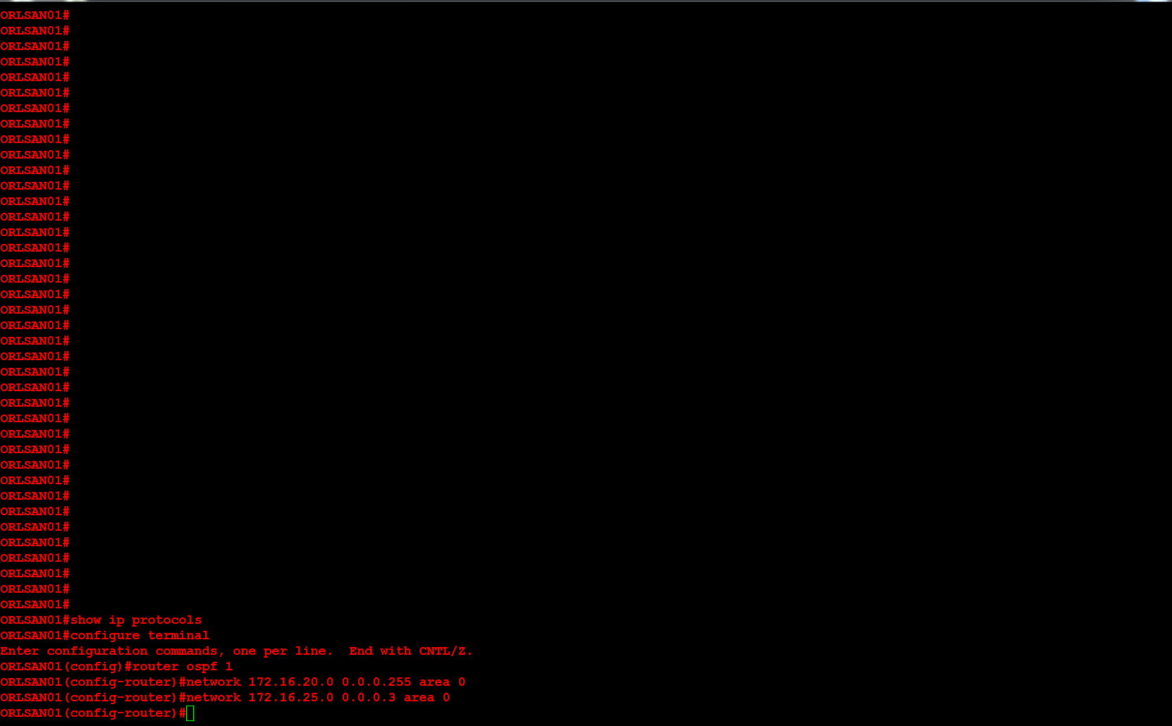
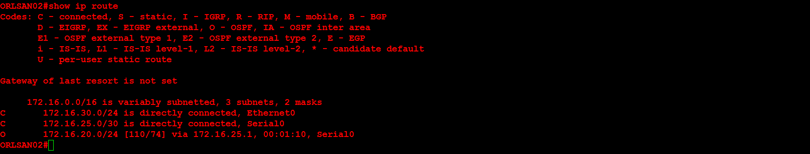
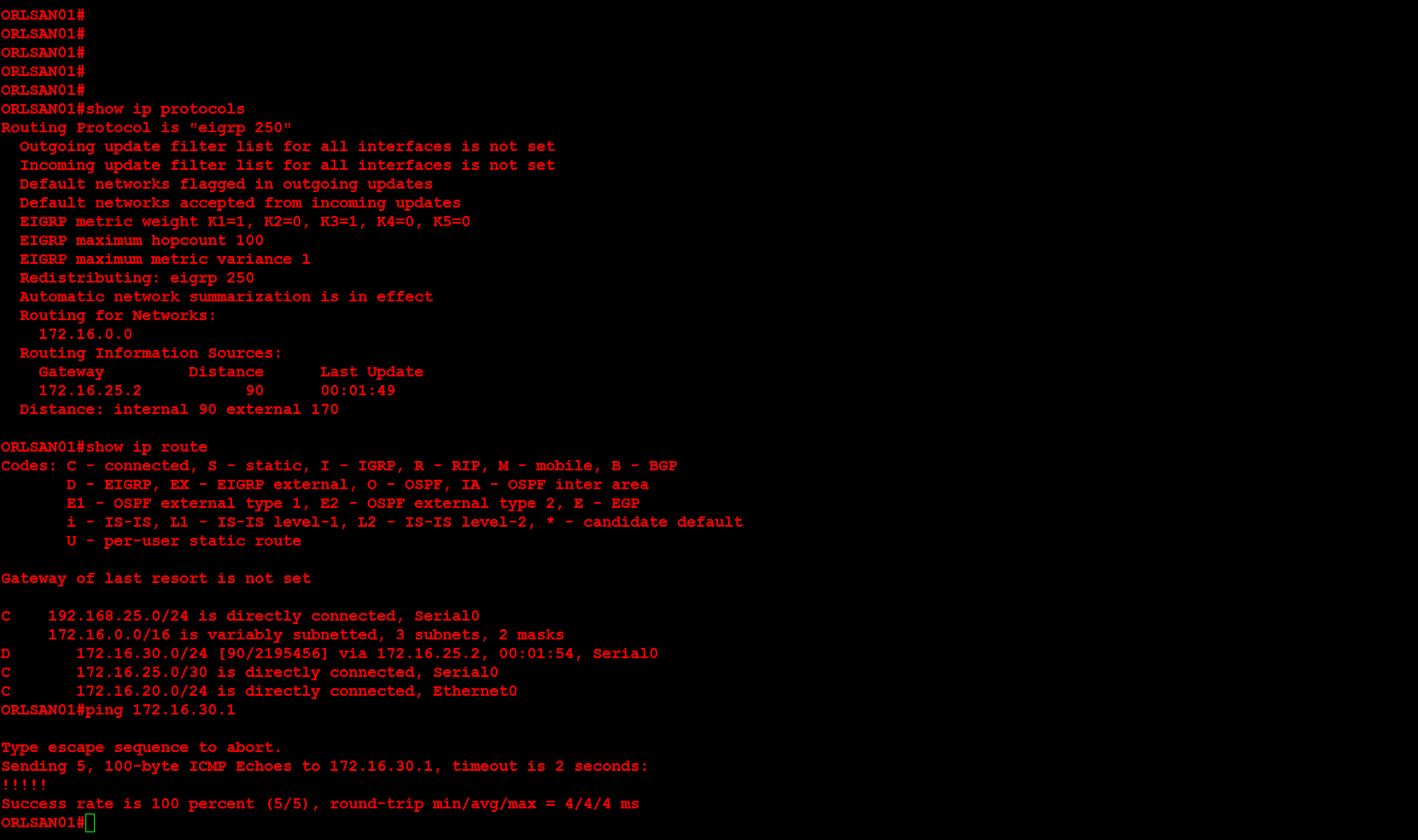
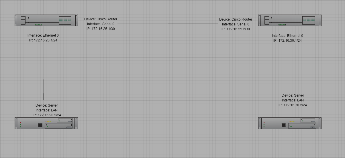
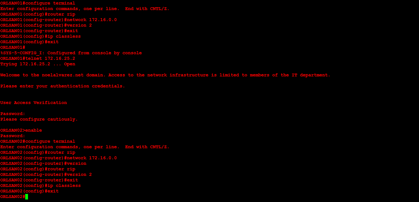
Next, I will configure ORLSAN02 with a static route to the 172.16.20.0/24 network, verify the route is in the routing table then ping 172.16.20.1.

17

Lastly, I will configure dynamic routing (RIPv2) on both routers, then verify that the RIP injected routes on ORLSAN01 and test the configuration by pinging 172.16.30.1 from the ORLSAN01 router.

18

19


Enjoy!


Cisco – Configuring Cisco WRVS4400N Router

At my current employer we recently had a Cisco Small Business WRVS4400N Wireless-N gigabit security router with VPN reach the end of it’s life. I replaced the wireless access point and configured it using the documentation I created in the past. Below you will find a basic step by step guide for configuring the device as a wireless access point.

NOTE: Please keep in mind that this is a very basic configuration and your configuration should be planned with careful considering to your Information Technology (IT) infrastructure. Additionally, I have modified the input of the actual configuration for security purposes.

1. The default Internet Protocol (IP) of the device is 192.168.1.1/24. You may manually configure the IP address of a Windows host to 192.168.1.2/24 in order to connect to the device. The default username is admin and the default password is admin.

00


2. Upon logging into the device you will see the following web page.

01


3. Navigate to the Administration > Management page and configure the Router Username: and Router Password:. It is widely considered a best practice to change the default username and password in order to prevent unauthorized users from logging into the device.

02


4. Navigate to the Setup > LAN page and configure the Local IP Address: and Subnet Mask: of the device. In our environment we have an existing Dynamic Host Configuration Protocol (DHCP) server so the DHCP Server: settings under the Server Settings (DHCP) menu is configured as a DHCP Relay.

03

5. Navigate to the Setup > Time page and configure the time settings for the device. I chose to use the Set the local time using Network Time Protocol (NTP) automatically setting. Our Time Zone: setting is (GMT-05:00) Eastern Time (US & Canada).

04

6. Under the Wireless > Basic Settings page configure the Wireless Network Mode:, Wireless Channel: and the SSID settings.

05

7. Under the Wireless > Security Settings page configure the Security Mode: and Shared Secret: for the SSID configured in step 6.

06

8. I recommend you backup the configuration by navigating to Administration > Backup & Restore. Once you are redirected to this page click the Backup button and specify the directory where the backup configuration will be saved. I did have a previously saved backup configuration but I configured this Cisco wireless access point manually in order to document the process on this webpage.

07

Enjoy!