VMware ESXi 5 – iSCSI Configuration

You may use the following method to connect your VMware ESXi 5.x host to an iSCSI SAN. Please keep in mind that this post assumes you have configured the SAN to allow the VMware host access to the appropriate LUN(s).

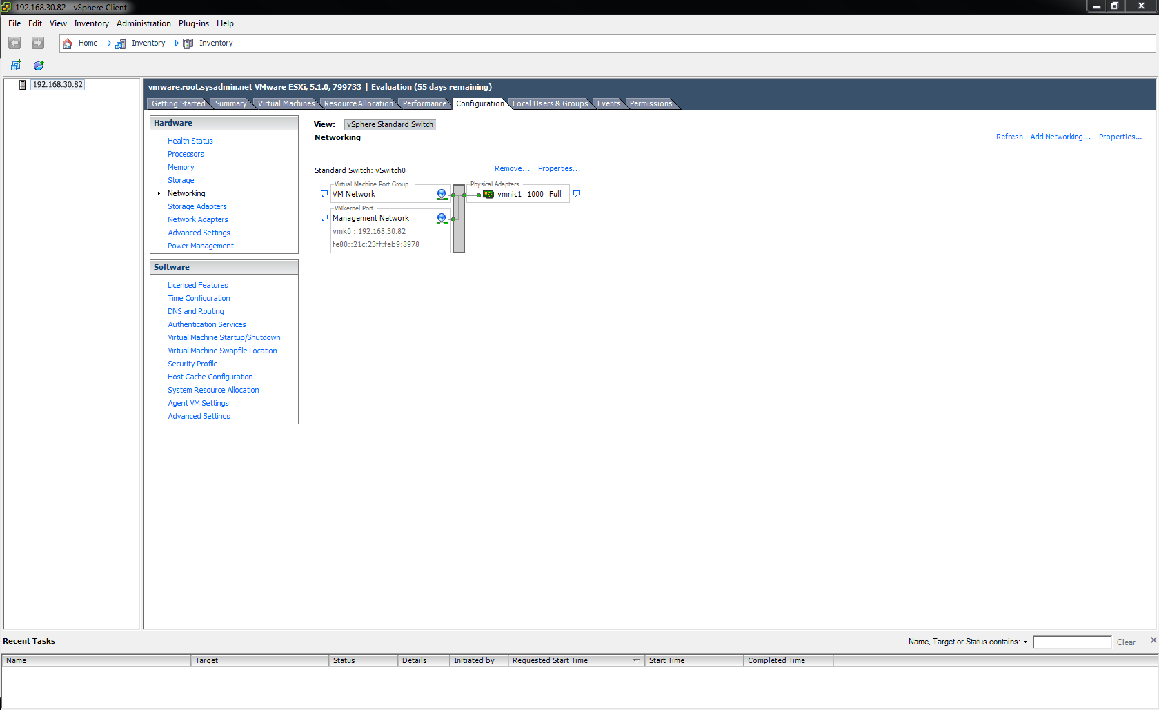
After logging into the vSphere Client navigate to Configuration > Networking then click Add Networking.

00

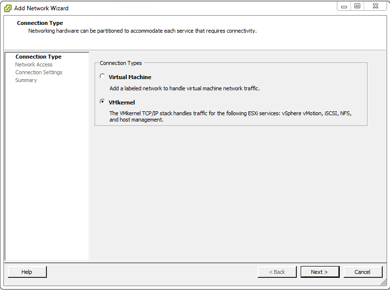
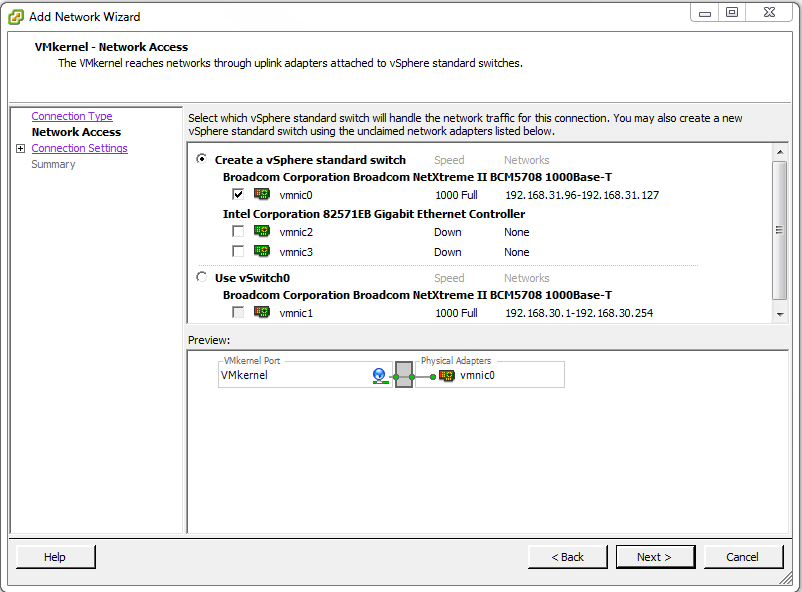
Under Connection Types select VMkernel then click Next >.

01

Select the vmnic that will be used for iSCSI traffic then click Next >. In this example it is vmnic0.

02

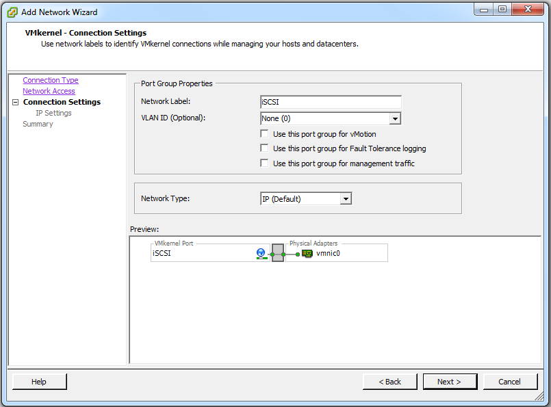
Type iSCSI for the Network Label: setting then click Next >.

03

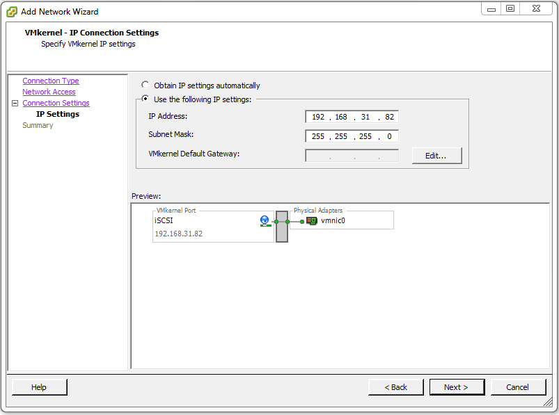
Select Use the following IP settings: and enter the correct Internet Protocol (IP) address and subnet mask for your particular network then click Next > (no VMkernel Default Gateway: setting is necessary because the iSCSI traffic will exist on the same local network). In this example the IP address is 192.168.31.82 and the subnet mask is 255.255.255.0. The iSCSI traffic will exist on the 192.168.31.0/24 network.

04

On the Ready to Complete page click Finish.

05

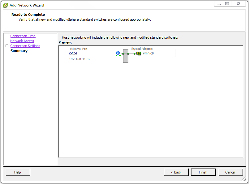
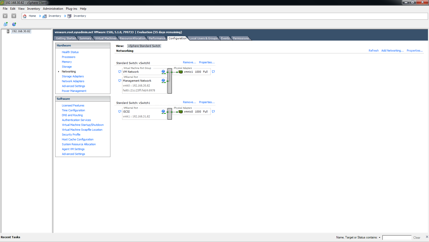
On the  Configuration > Networking page you will now see a new switch labeled Standard Switch: vSwitch 1.

06

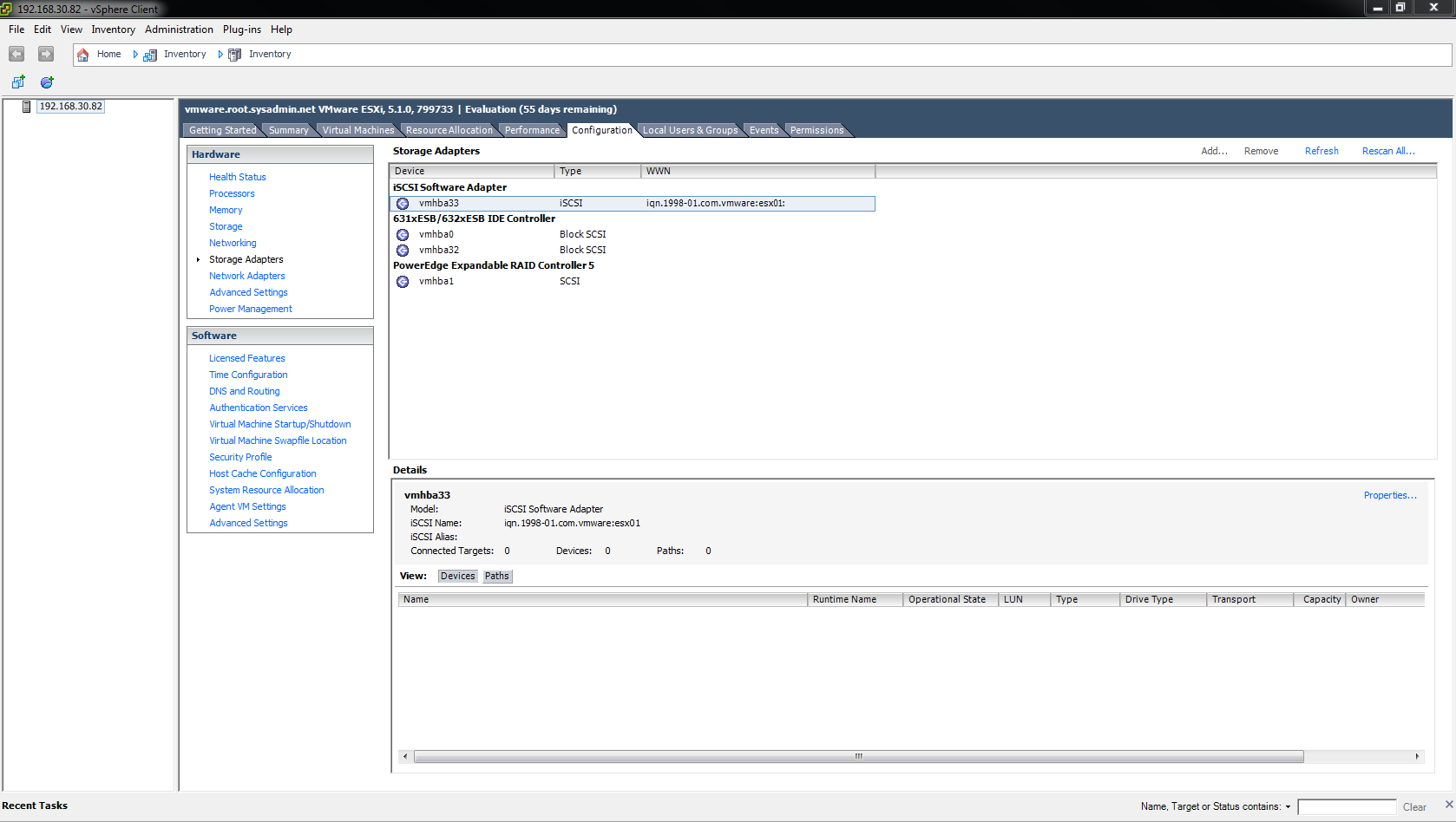
Next, navigate to Configuration > Storage Adapters. Right click the iSCSI Software Adapter (vmhbaxx) and select Properties….

07

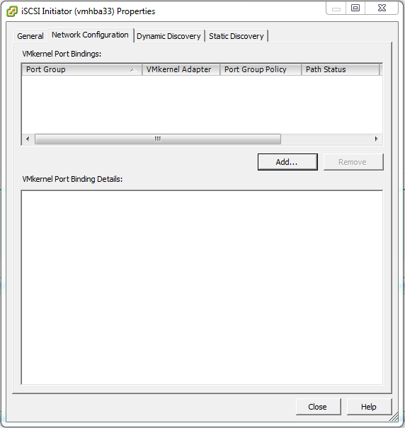
Under the Network Configuration tab click Add….

08

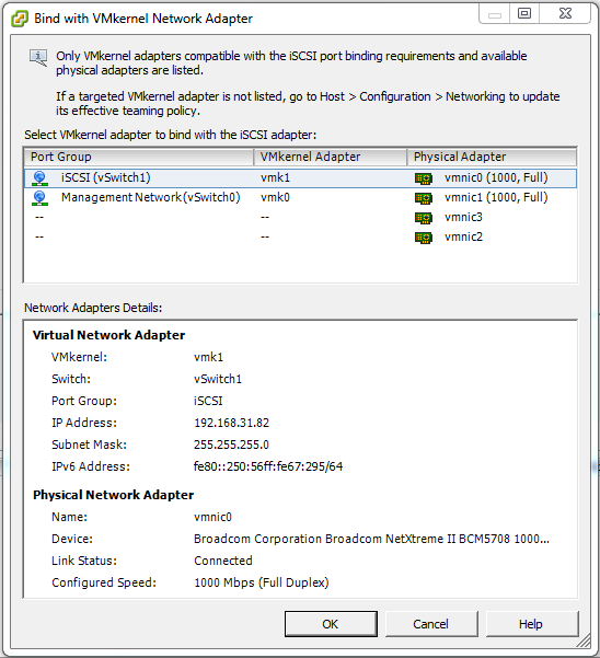
Under Port Group select iSCSI (vSwitch 1) and click OK.

09

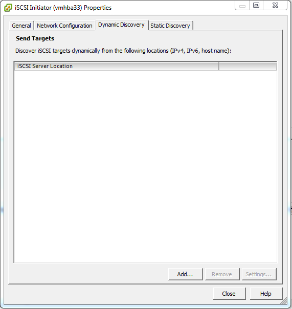
On the Dynamic Discovery tab click Add….

10

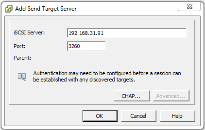
In the iSCSI Server: field type the IP address of the iSCSI target server then click OK. In this example it is 192.168.31.91.

11

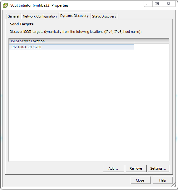
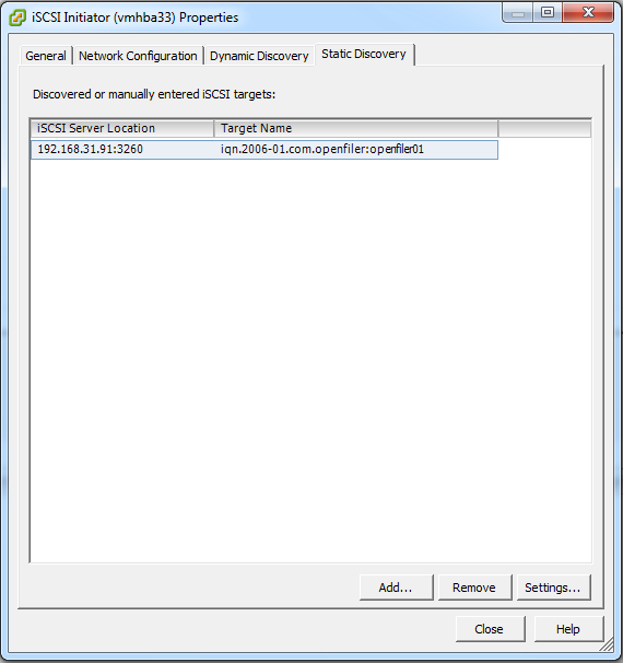
The IP address of the iSCSI targer server should now be visible under the Dynamic Discovery and Static Discovery tab. If so, click Close.

12

13

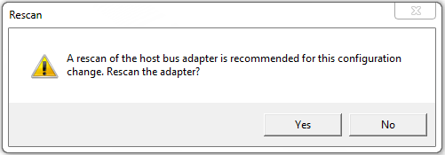
Select Yes when prompted to rescan the host bus adapter.

14

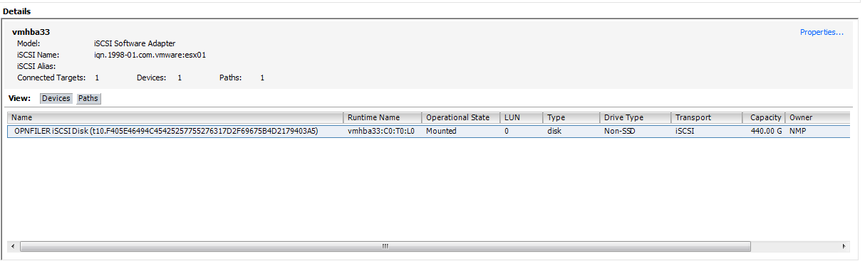
Under the Details section of the window you should now see the LUN(s) that have been configured for use.

15

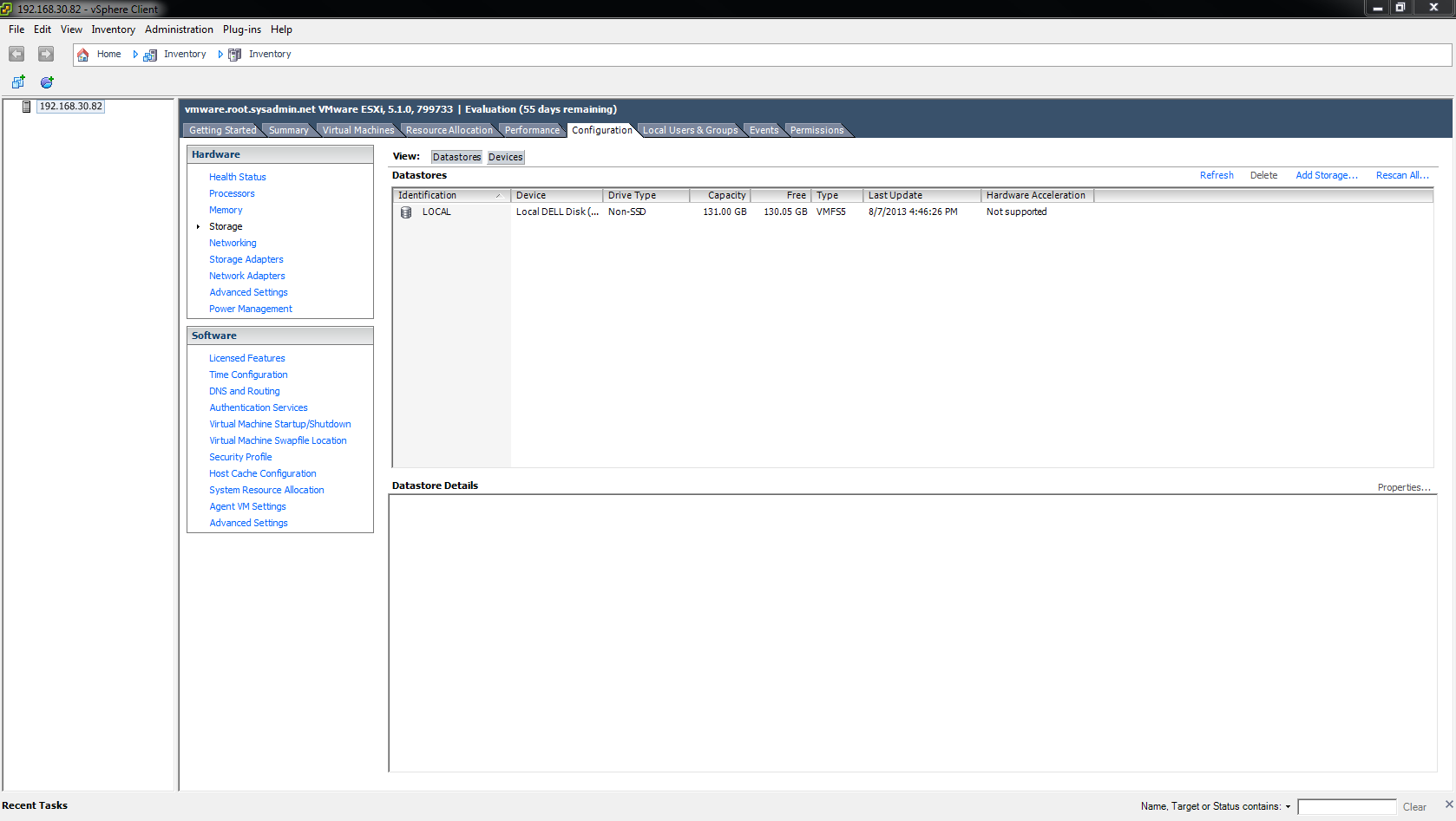
Next, navigate to Configuration > Storage then click Add Storage….

16

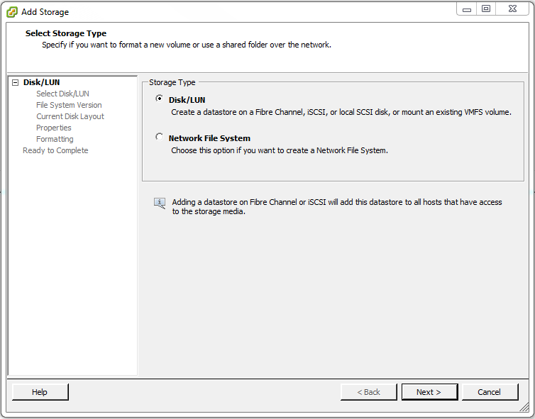
Under Storage Type select Disk/LUN then click Next >.

17

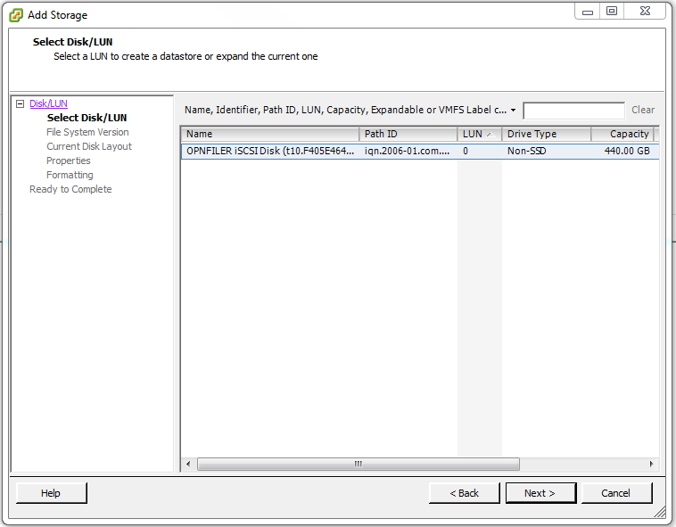
Select the LUN(s) then click Next >.

18

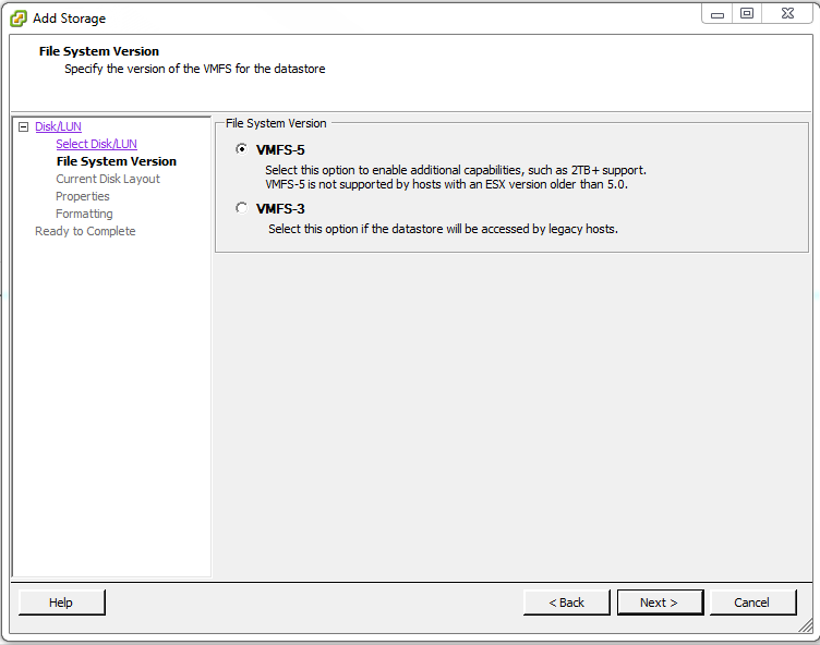
Under File System Version select VMFS-5 then click Next >.

19

After reviewing the configuration click Next >.

20

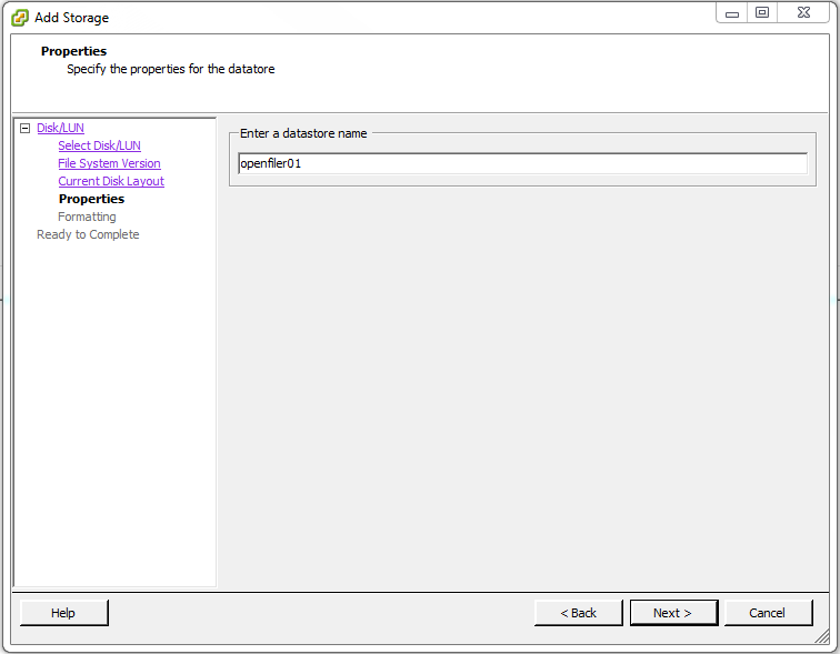
Enter a datastore name that will identify the datastore then click Next >. In this I chose openfiler01 because that is the hostname of the iSCSI SAN used in this example.

21

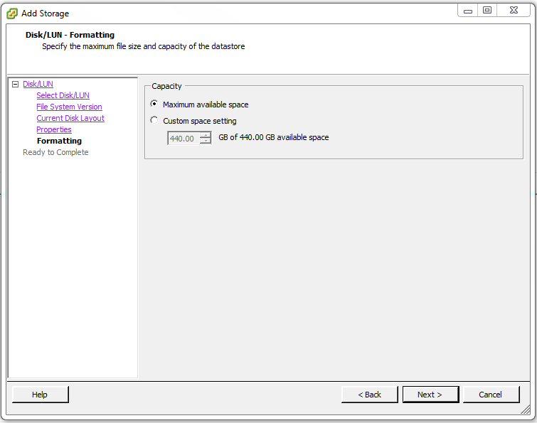
Under Capacity select Maximum available space then click Next >.

22

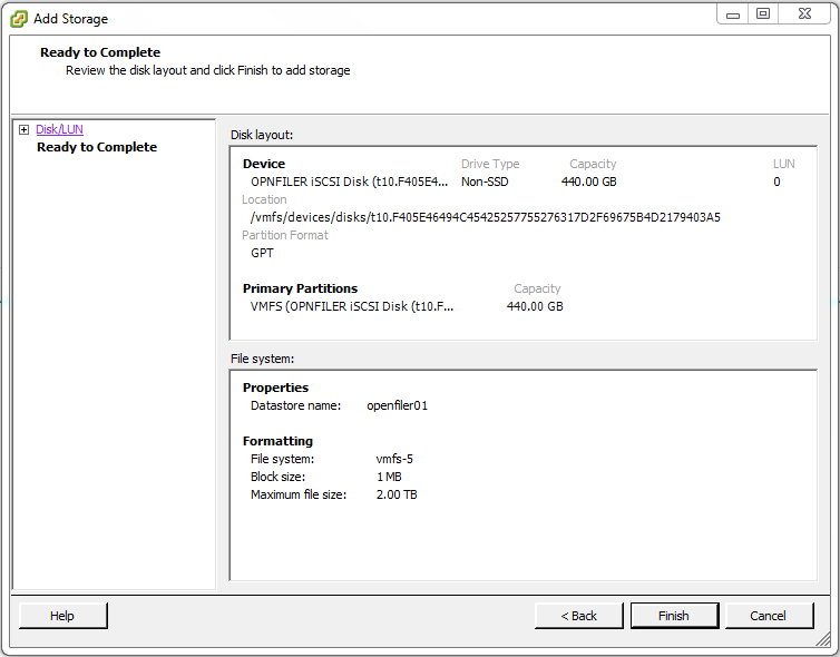
On the Disk layout: page click Finish.

23

After the VMFS datastore is created it will be visible on the Configuration > Storage page.

24

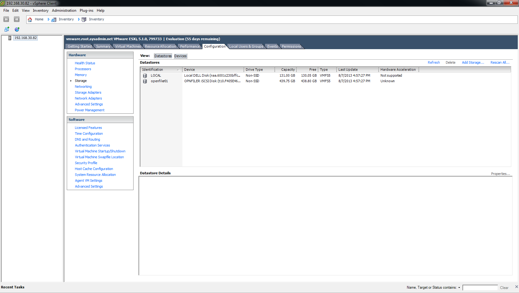
Now when you create virtual machines you may store them on this VMFS datastore.

This completes the process.

Enjoy!


Microsoft Windows Storage Server 2012 – Install iSCSI Target Role

You may use Microsoft Windows Storage Server 2012 as an iSCSI Storage Area Network (SAN). To do so you must install the iSCSI Target feature. Below you will find a step-by-step guide to installing this feature.

On the Server Manager > Dashboard page select Manage > Add Roles and Features.

00

On the Before you begin page click Next >.

01

On the Installation Type page select Role-based or feature-based installation and click Next >.

02

On the Server Selection page select the server that you would like to enable the iSCSI Target. In this example, I will be choosing iSCSI01. After selecting the server click Next >.

03

On the  Server Roles page select File And Storage Services (Installed) > File and iSCSI Services > iSCSI Target Server. When the Add features that are required for iSCSI Targer Server? dialog box appears click Add Features. When you return to the Server Roles page click Next >.

04


05


06

On the Features page click Next >.

07

On the Confirmation page click Install.

08

On the Results page verify that the installation was successful (i.e. Installation succeeded on server), then click Close.

09

This completes the installation.

Enjoy!


Microsoft Outlook 2010 – Drag and Drop Malfunction

Have you ever been unable to drag and drop emails in Microsoft Outlook 2010? If so, pressing the Esc key a few times will actually resolve this issue.

Enjoy!


Microsoft Active Directory – Windows Server 2008 R2 Enterprise Domain Controller (DC) Deployment

Implementing a Microsoft Active Directory (AD) domain allows you to centrally manage almost all aspects of a network. For this reason, domains have been used in many corporate networks. In order to implement an AD domain you must have a Domain Controller (DC). This tutorial will provide you with a basic step-by-step guide on deploying a Microsoft Windows Server 2008 R2 Enterprise edition DC.

To begin, type dcpromo in the start menu.

00

In the Active Directory Domain Services Installation Wizard, initial page, click Next >.

01

In the Operating System Compatibility page click Next >.

02

In this example, the domain will be the first in a new forest so we will select Create a new domain in a new forest. After selecting that option click Next >.

03

In the Name the Forest Root Domain dialog box type the fully qualified domain name (FQDN) for this domain. For this example I have chosen root.sysadmin.net (but you may chose a different FQDN). After you enter the FQDN click Next >.

04

In the Set Forest Functional Level page select Windows Server 2008 R2 under the Forest functional  level: option then click Next >.

05

In the Additional Domain Controller Options page select the check box next to DNS Server to make this DC controller a Domain Name System (DNS) server then click Next >.

06

If you receive a dialog box stating A delegation for this DNS server… then click Yes.

07

In the Location for Database, Log Files, and SYSVOL dialog box, accept the defaults (as this is a very basic configuration), and click Next >.

08

In the Directory Services Restore Mode Administrator Password page type a password of your choosing then click Next >.

09

In the Summary page I recommend clicking Export settings… and saving the file. This may be used in the future for documentation, etc. After you export the settings click Next >.

10

At this point you will see a new dialog box appears as Active Directory Domain Services are being configured.

11

In the Completing the Active Directory Services Installation Wizard dialog box click Finish.

Select Restart Now in the following prompt.

12

After the server restart and you login, open the Event Viewer and view the Directory Services logs. In particular, looking for Event Viewer ID 10001394.

13

14

This completes the Microsoft Active Directory Domain Controller deployment.

Enjoy!


Cisco – OSPF Routing Protocol Configuration

Open Shortest Path First (OSPF) is an open standard routing protocol that may be implemented on routers from multiple vendors. In this example the OSPF routing protocol will be implemented on two (2) Cisco routers.

First, I will issue the show ip protocols command to verify there is no existing routing protocol running on the router. If there was another routing protocol with a lower administrative distance (AD) such as IGRP or EIGRP then the OSPF configuration would have been void until IGRP or EIGRP were turned off.

00

Next, I will enter global configuration mode by entering the command configure terminal. After that I enabled the OSPF routing protocol with the command router ospf 1. The number “1” is the process ID for OSPF and is only locally significant.

01

Next, I specified the networks to be advertised (172.16.20.0/24 and 172.16.25.0/3) using wildcards and placed them in area 0.

02

Next, I entered the command show ip protocols to verify that the OSPF routing protocol is enabled on this router. Additionally, I can verify that it is running under process “1” and verify the networks that are being advertised.

03

Next, I configured the OSPF routing protocol, using the same method in the previous steps, on the other router in this example.

04

Now I will verify that the 172.16.20.0/24 is being advertised by the ORLSAN01 router by enter the command show ip route.

05

Additionally, I can ping the ethernet 0 interface (172.16.20.1) on ORLSAN01 to verify Internet Protocol (IP) connectivity.

06

I will now make my way back to ORLSAN01 and view the routing table to verify that the 172.16.30.0/24 network from ORLSAN02 is being advertised. As in my previous example I will ping the ethernet 0 interface (172.16.30.1) on ORLSAN02 to verify IP connectivity.

07

They were no dropped packets in either example so this configuration is successful.

Enjoy!


Cisco – EIGRP Routing Protocol Configuration

You may use the following method to configure Enhanced Interior Gateway Routing Protocol (EIGRP) on your Cisco router(s).

Begin by entering privileged exec mode on your Cisco router by using the enable command.

00

Enter global configure mode by using the command configure terminal.

01

Type the command router eigrp [as] where [as] is the autonomous system number. The autonomous system number may be any number between 1 – 65535. The important part to remember is that the autonomous system numbers must be identical on each router in order for the EIGRP routers to exchange routing information.

02

Use the network x.x.x.x command to advertise the networks of your choosing where x.x.x.x is the classful address range of that particular network. In this particular example this router has 172.16.20.0/24 (ethernet 0) and 172.16.25.0/30 (serial 0) configured so I used the classful address range 172.16.0.0.

03

After configuring the other router in this example, with EIGRP and autonomous system number 250, we can now verify our configuration with the show ip protocols, show ip route and ping commands.

04

The show ip protocols command will display information regarding each routing protocol that is configured on your router. The show ip route command will display the routing table on your router. In this example, the C represents directly connected networks and the D represents the EIGRP advertised routes. Lastly, I used the ping command to verify network connectivity between the two routers.

Enjoy!


Windows Server 2012 – Create and Configure Shares

You may use the following method to create and configure a share (with basic settings) in Windows Server 2012.

Begin by opening the Server Manager then navigating to File and Storage Services > Shares.

00

On the Shares page click TASKS > New Share….

01

This is a very basic configuration (designed to get you accustomed to the platform) so in the New Share Wizard on the Select Profile page choose SMB Share – Quick then click Next >.

02

On the Share Location page choose the location of the share then click Next >. In this example, I chose a custom location of E:\shares.

03

On the Share Name page type the name of the share and add a description (optional) then click Next >.

04

On the Other Settings page leave the default setting (Allow caching of share) then click Next >.

05

On the Permissions page you may click the Customize permissions… button the create a custom set of permissions for your share. After customizing click Next >.

06

On the Confirmation page verify your configuration then click Create.

07

The Results page will inform you if the creation of the share was successful or unsuccessful. In this example, the creation was successful so click Close.

08

Enjoy!


Microsoft Windows Server 2012 – Distributed File System (DFS) Configuration

Distributed File System (DFS) allows you to share folders that are located on multiple servers using a consistent and logical namespace. Microsoft Windows Server 2012 allows you to add the DFS role (namespace and replication). After you add the DFS role you may use the following method to configure the namespace for your organization.

In Microsoft Windows Server 2012 select DFS Management on the start menu.

00

In the DFS Management console right click Namespaces and select New Namespace….

06

In the New Namespace Wizard dialog box, on the Namespace Server page click Browse…, then begin typing the name of the server that will host the name space, click OK. Lastly, click Next > on the New Namespace Wizard dialog box.

01

On the Namespace Name and Settings page enter the settings for your organization then click Next >. For this example I will type shares in order to make the namespace \\root.sysadmin.net\shares.

02

On the Namespace Type page select the appropriate setting for your environment then click Next >. In this example I will be using Domain-based namespace.

03

On the Review Settings and Create Namespace page review your settings then click Create, if they are correct.

04

On the Confirmation page you will be informed if the namespace was added successfully. If it was successful then click Close.

05

Next, right click the newly created namespace in the DFS Management console and select New Folder….

10

In the New Folder dialog box enter the next folder in the namespace and add it’s target by clicking Add… and adding the path in the Add Folder Target dialog box, then click OK.

07

08

Lastly, test the DFS configuration by connecting to the share using the newly created DFS namespace.

Enjoy!


Virtual Drive – Solution

If you ever find yourself in a situation where you need to mount an ISO you may use the application Virtual CloneDrive. The link below will provide a download link:

http://www.slysoft.com/en/download.html

Enjoy!


Microsoft Windows Server 2012 – Install Distributed File System (DFS) Role


You may use the following method to install the Distributed File System (DFS) role on a server running the Windows Server 2012 operating system (OS). The link below will direct you to a Microsoft TechNet article that provides a detailed description of DFS.

In the Microsoft Windows Server 2012 Server Manager dashboard click Add roles and features.

00

In the Add Roles and Features Wizard > Before You begin page click Next >.

01

On the Installation Type page select Role-based or feature-based installation and click Next >.02

On the Server Selection page select the appropriate server and click Next >.03

On the Servers Roles page navigate to File And Storage Services > File and iSCSI Services and select both DFS Namespaces and DFS Replication. When the Add features that are required for DFS Namespaces? dialog box appears click Add Features. Then, click Next >.040506

On the Features page click Next >.07

On the Confirmation page select the check box to Restart the destination server automatically if required (optional) and click Install.08

Click Close on the Results page after the installation succeeds.09

Lastly, you may configure your DFS namespace by clicking the DFS Management icon on the Start menu. This will open the DFS Management snap in.10

11

Enjoy!